This tutorial is a work in progress! Feel free to nudge us or ask questions.
Overview
- Install software packages and libraries
- Arduino IDE
- Northern Widget board definitions
- ATTinyCore microcontroller definitions
- Third-party microcontroller definitions (if needed for sensors)
- Northern Widget libraries and dependencies
- Clock-setting GUI
- Programming
- Materials needed
- Bootloading data logger (ICSP)
- Uploading code to data logger (USB or ICSP)
- Programming sensors (ICSP)
- Setting the clock (USB)
- Telemetry (Okapi only)
- Recording and plotting data
- Field assembly
- Enclosure
- Drill holes for wires
- Affix logger + batteries
- Sensor mounting (posts, hose clamps, pipe, etc.)
- Enclosure
- Deployment
While superceded by more recent data-logger models, the ALog README has some of our most complete documentation. We’re going to reuse some of it as we build this page, but want to give you early go-getters a link to start you out.
Step 1: Install software packages and libraries
Helpful external Arduino tutorials and documentation
We use Arduino because it is a popular system with a large user base, mature software libraries, and extensive support! The information here is tailored a bit more to our sensors and data loggers, but is not as extensive as help available elsewhere on the internet. Here are some curated links to guides:
Adafruit: Learn Arduino
Official Arduino programming reference
Adafruit: Adding Third-Party Boards
Arduino software, libraries, and boards definitions
Arduino is an open-source electronic hardware development platform. For more information on Arduino, go to https://www.arduino.cc/.
Download and install the Arduino IDE
The Arduino IDE (Integrated Development Environment) is the current programming environment we use to write and upload programs to the Northern Widget sensors and data loggers. (Other options exist, but this is the most beginner-friendly.) We haven’t yet tested the brand-new web editor, so we’ll be suggesting an old-fashioned download. And if you’re deploying these in the field, you’ll need the downloaded version! To download, go to https://www.arduino.cc/en/Main/Software.
Note: For Windows users, go for the standard download, not the “app”.
Set up the Northern Widget board definitions
Note: This step is required only if you are using a Northern Widget data logger (Margay or Okapi). You may skip this step if you are using a standard Arduino or other board for which you already have support through the Arduino IDE.
The Northern Widget boards are third-party Arduino boards, so you’ll have to set up support for these boards yourself. We’ve made a pretty thorough walkthrough that you can view here at https://github.com/NorthernWidget/Arduino_Boards.
Add board definitions for the ATTinyCore microcontrollers
Note: This step is required only if you have to upload firmware to Northern Widget sensors.
You can follow the instructions to download and install ATTinyCore microcontroller support in the Arduino IDE, but for clarity here are some basic instructions:
- Go to the ATTinyCore microcontroller GitHub page, here you will find all details about ATTinyCore
- Scroll down and click on the “Installation” link right above the “Wiring and required components link”
- From there, follow the installation instructions based on your preferred installation method - either through the Arduino Boards Manager or manually
Install all Northern Widget libraries and their dependencies
We have a set of custom firmware libraries designed to make your life easier.
The only step that you have to take is to install them. Go to
https://github.com/NorthernWidget/NorthernWidget-libraries and follow the
instructions in the README to add these to your libraries folder.
Install the graphical user interface (GUI) to set the logger’s clock
Follow the instructions on the SetTimeGUI GitHub page.
Step 2: Programming
Materials needed:
- Your PC with the software/libraries loaded listed in Step 1:
- Arduino IDE
- Northern Widget board definitions
- ATTinyCore microcontroller board definitions (required only for uploading firmware to Northern Widget sensors)
- Northern Widget libraries
- SetTimeGUI
- Arduino-compatible device (e.g. your logger)
- A programming cable, which can be:
- A USB cable that can attach to this device (current Northern Widget data loggers use a USB type-A to micro-B cable, similar to all but the newest Android smartphones)
- An in-system programmer (ISP) that attaches to a 6-pin header on the board
- Examples:
- The official AVR ISP mkII (no longer produced but available used)
- Using an Arduino as an ISP
- The versatile Olimex AVR-ISP-MK2
- The Adafruit USBtinyISP
- A USB type-A to USB type-B (not micro-B!) cable is required for all ISPs listed here, but be sure to check your own for required cables/any additional cables if using a different ISP
- Ensure that you have the correct cables/adapters to attach the ISP to your device - for example, attaching the Olimex AVR-ISP-MK2 to many Northern Widget devices requires a 10-pin to 6-pin adapter in order to connect the ICSP10 output on the ISP to the 6-pin input on the board
- Examples:
Note: If you are just programming an Arduino board or data logger, which already has a bootloader installed (if you don’t know what this is, it probably has it), then all you need is your PC, the board and the USB cable.
The basics of uploading programs
Arduino programs, often called “sketches”, are how you tell an Arduino device what to do. Here is some information to get you started.
Terminology
- Microcontroller: A computer chip that integrates a processor, memory, and methods to take electrical inputs and send electrical signals.
- Software: A program that involves active changes and interactions. This typically exists on a computer and runs within an operating system. An example here is the Arduino IDE.
- Firmware: A program that is uploaded once to a computer or microcontroller and then executes the same set of commands. Any code that you upload to an Arduino-compatible device is an example of firmware.
- Sketch: The Arduino name for the C++ source code in which you write a program.
- Bootloader: A small piece of firmware that is installed in a specific portion of the microcontroller’s memory. In the case of Arduino-compatible devices, this is almost always to allow the device to be programmed via USB.
- Function: A defined section of code that completes some task and optionally returns output.
- Class: A container that holds functions and variables. An object is a particular instance of a class (e.g., the class is Cap’n Crunch (or pick another cereal or item); my box of Cap’n Crunch is an object).
- Library: A piece of pre-written code that you can
#includewithin a program (such as an Arduino sketch) in order to use its functions. This typically helps to shorten the length of your sketches by hiding a lot of complicated code and exposing it as functions that can be called in just a single line of code. It contains a*.hand a*.cppfile and typically resides within the “libraries” folder of your Arduino app (in the case of Mac) or directory (in the case of Linux or Windows).
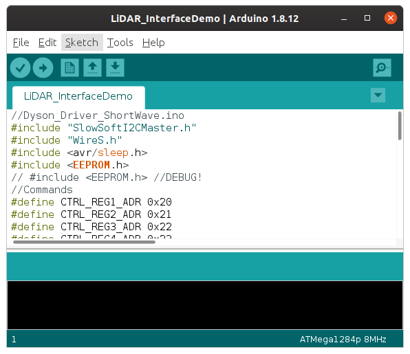
Arduino starting screen
When you open the Arduino IDE, you will see a default blank “sketch”:
void setup() {
  // put your setup code here, to run once:

}

void loop() {
  // put your main code here, to run repeatedly:

}
setup() and loop() are both functions. These are specific sets of code that are executed when their names are called in the code. These two functions are special in that:
- Every Arduino program must have them.
- They do not need to be called by code that you write: Arduino automatically interprets and, indeed, requires that these be included.
- Everything inside the curly braces after
setup()is run once, when the data logger starts running. - Everything inside the curly braces after
loop()is run continuously, aftersetup(), until the Arduino device loses power.
- Everything inside the curly braces after
In addition:
- You may include other code libraries and declare variables before these functions.
- You may include additional functions after these functions.
Bootloading
Note: If you are just programming an Arduino board or data logger, which already has a bootloader installed (if you don’t know what this is, it probably has it), then please proceed to the “Uploading code to the Arduino-compatible device” section below.
In-system programmer
Important note for Linux users: You must supply permissions to the Arduino IDE for it to be able to use the ICSP, or you will have to run it using sudo. The former option is better; the latter is easier in the moment.
In order to bootload your logger or sensor you will need to use a special device called an “in-circuit system programmer” (or just “in-system programmer” or “ISP”) that attaches to a 2x3 header, with either 2.54 mm (0.1”) or 1.27 mm (0.05”) spacing. ISPs may be used in Northern Widget devices for:
- uploading a bootloader, or
- uploading firmware for a sensor.
Many devices exist to upload bootloaders or firmware, including:
- The official AVR ISP mkII (no longer produced but available used)
- Using an Arduino as an ISP
- The versatile Olimex AVR-ISP-MK2
- The Adafruit USBtinyISP
Note: Be sure to download and/or update drivers for your ISP.
In either case, you follow these two steps:
- Plug your ISP of choice into your computer (via a USB cable) and plug the ISP into your device (via the 6-pin header). There are two ways to place it on; the header is aligned such that the ribbon cable should be facing away from the board while programming. If this fails without being able to upload, try flipping the header around. This should both power the board and provide communications.
- Go to Tools –> Programmer and select the appropriate programmer based on what you are using.
To upload the bootloader, you go to Tools –> Burn Bootloader. If you are doing this on an Arduino or data-logger board, you may have to plug in the USB cable to supply enough power and to go to Tools –> Port and select the proper serial port for your device. (It is not programmed via the serial port though, so I (Wickert) do not understand why you sometimes have to do this.)
Lights should flash on the programmer and board and a message should appear in the Arduino IDE that tells you whether or not you have succeeded. If it fails, try these approaches in order:
- Try flipping around the ISP (also called “ICSP”) attachment;
- Make sure that all of your USB-cable connections are secure;
- Double-check your drivers are up-to-date;
- Double-check if administrator permissions are needed for the Arduino IDE, if so give them;
- Desperate internet searching.
Uploading code to the Arduino-compatible device
Once your code is written – either as a copy/paste of this or as your own – save your code. All Arduino sketches need to be within their own folder; the Arduino IDE will ensure that this happens. After saving, you can upload in one of two ways:
If you upload the above code to an Arduino device, it will do nothing, because the code contains no instructions.
Uploading via USB
If you are programming the board via USB, hit the “upload” button (right arrow) to load the code to the board. (The check mark to the left will test if your code compiles.)
 to board.")
Upload the Arduino sketch to the board. (Pay no mind to the specific text; this comes from our old ALog data logger.)
Uploading via In-System Programmer (ISP)
If you are uploading firmware using the in-system programmer, you then go to Sketch –> Upload Using Programmer. After several seconds, you learn whether you succeeded or failed. Hopefully it worked!
Programming Northern Widget data loggers
Each of our data loggers’ README.md pages contains information on programming them, with (at the time of writing) the Okapi data logger having a complete example. For reference, these data loggers are:
- Margay: Microamp-power. (More inforamtion available at the Margay Library page)
- Okapi: Telemetry-enabled with integrated solar charging.
Margay: “No sensors” example
A simple program for a Margay data logger, connected to no sensors
/*
 * Margay example: no sensors attached
 */

 #include "Margay.h"
 // Include any sensor libraries.
 // The Northern Widget standard interface is demonstrated here.
 //Sensor mySensor;

 // Instantiate classes
 // Sensor mySensor (for any Northern Widget standard sensor library)
 Margay Logger; // Margay v2.2; UPDATE CODE TO INDICATE THIS

 // Empty header to start; will include sensor labels and information
 String header;

 // I2CVals for sensors
 // Add these for any sensors that you attach
 // These are used in the I2C device check (for the warning light)
 // But at the time of writing, the logger should still work without this.
 uint8_t I2CVals[] = {};

 // Number of seconds between readings
 // The Watchdog timer will automatically reset the logger after approximately 36 minutes.
 // We recommend logging intervals of 30 minutes (1800 s) or less.
 // Intervals that divide cleanly into hours are strongly preferable.
 uint32_t updateRate = 60;

 void setup(){
     // No sensors attached; header may remain empty.
     // header = header + mySensor.getHeader(); // + nextSensor.getHeader() + ...
     Logger.begin(I2CVals, sizeof(I2CVals), header);
 }

 void loop(){
     Logger.run(update, updateRate);
 }

 String update() {
     initialize();
     //return mySensor.getString(); // If a sensor were attached
     return ""; // Empty string for this example: no sensors attached
 }

 void initialize(){
     //mySensor.begin(); // For any Northern Widget sensor
                         // Other libraries may have different standards
 }
Okapi: full breakdown
This example is a direct copy/paste of https://github.com/NorthernWidget-Skunkworks/Project-Okapi#how-to-write-a-program.
The below program is an example that you can copy and paste directly into the Arduino IDE in order to upload to your data logger. We’ll walk you through what each piece of the code is and does.
@awickert: use a more modern sensor library with appropriate camelCase.
Full program
/*
 * Okapi example: connected with a Walrus pressure--temperature sensor, often
 * used for water-level measurements, via the Longbow I2C/RS-485 translator.
 * Written by Bobby Schulz with a few comments added by Andy Wickert.
 */

#include "Okapi.h"
#include <TP_Downhole_Longbow.h>

TP_Downhole_Longbow Walrus; // Instantiate Walrus sensor; relict library name
Okapi Logger; // Instantiate data logger object

String Header = ""; // Information header; starts as an empty string
uint8_t I2CVals[1] = {0x22}; // I2C addresses of sensors

unsigned long UpdateRate = 60; // Number of seconds between readings

void setup() {
  Header = Header + Walrus.GetHeader();
  Logger.begin(I2CVals, sizeof(I2CVals), Header); // Pass header info to logger
  Init();
}

void loop() {
  Logger.run(Update, UpdateRate);
}

String Update()
{
  Init();
  delay(1500);
  return Walrus.GetString();
}

void Init()
{
  Walrus.begin(13, 0x22); // Instantiate Walrus (at address = 13)
                          // and Longbow Widget (at address = 0x22)
}
“Include” statements
#include "Okapi.h"
#include <TP_Downhole_Longbow.h>
These bring in the two code libraries involved, the former for the data logger and the latter for the sensors. This allows the user to access the classes and functions within these two libraries, as we will show in more detail below.
Instantiate a sensor object
TP_Downhole_Longbow Walrus; // Instantiate Walrus sensor; relict library name
Okapi Logger; // Instantiate data logger object
“Instantiating an object” means that we create our own specific versions of the a class of items. This can be thought of as: Breakfast myBreakfast. Breakfast is the general concept, but I create “myBreakfast”, which I can then modify. In this same way, “Logger” is what we call our Okapi data logger, and “Walrus” is what we call our “TP_Downhole_Longbow” sensor; this name is a holdover from an earlier design that is the ancestor of the Walrus. We can then access functions and variables within these two instantiated objects.
Declare the header string
String Header = ""; // Information header; starts as an empty string
We start with an empty header, but will soon add information to it.
Create a list of the I2C addresses of the sensors
uint8_t I2CVals[1] = {0x22}; // I2C addresses of sensors
This is the trickiest step. You need to know what the I2C address of your sensor is. You can skip this, but then the logger will not run a check to see if the sensor is properly connected.
Let’s make sure that we record this one each page, or find a way to replace this.
Declare the amount of time between logging events
unsigned long UpdateRate = 60; // Number of seconds between readings
This is the number of seconds between logging events. If it takes 2 seconds to record data, make sure that you give the logger at least 3 seconds between events. The maximum logging time is set by the watchdog timer, which is around 34 minutes on Margay (making 30 minutes a practical cap). On Okapi, the attached telemetry board may provide a watchdog timer, which is activated when the board is activated and therefore does not restrict the logging intervals.
@BSCHULZ1701: Is there an external WDT on Okapi?
setup() step: runs once at the start
void setup() {
  Header = Header + Walrus.GetHeader();
  Logger.begin(I2CVals, sizeof(I2CVals), Header); //Pass header info to logger
  Init();
}
setup() is a special function that runs just once when the logger boots up. In this case, it first adds the Walrus’ header to the header string. GetHeader() is a standard function that lies within each of our sensor libraries and returns this header information as a String. We then pass the header and the I2C values to the Okapi library’s begin() function. This sets up the header and prepares the data loger to record data. Finally, this function calls Init(), which we skip ahead to describe immediately below.
(awickert): I still don’t understand why we have to pass
sizeof()and can’t just compute that within the function.
Init() function: skipping ahead to understand setup()
void Init()
{
  Walrus.begin(13, 0x22); // Instantiate Walrus (at address = 13)
                          // and Longbow Widget (at address = 0x22)
}
The Init() function calls the begin() function, standard within each Northern Widget sensor library, to instantiate the connection ports (e.g., I2C, RS-485) used to communicate between the sensor and the logger. In this case, there is only one sensor, but two ports are needed: An RS-485 signal goes from the Walrus to the Longbow Widget, which then converts the signal into an I2C signal with its own address. The reason for this is that an I2C signal can travel only ~3 m, but an RS-485 signal can travel ~100 m.
loop() step: keeps running until stopped
void loop() {
  Logger.run(Update, UpdateRate);
}
The loop calls the main function of the Okapi library, run(), repeatedly. This puts the logger into a low-power sleep mode and wakes it up only when interrupted by the clock or the “LOG” button. Update refers to the function described immediately below. UpdateRate is our logging interval defined above.
Update() function: Gives data for the logger to record
String Update()
{
  Init();
  delay(1500);
  return Walrus.GetString();
}
The Update() function first calls the Init() function to be sure that the sensor is ready to log. It then in this case delays 1500 milliseconds; this is an ad-hoc solution to the question of how long it takes the pressure transducer to settle after being started up, and is a safe large amount of time. This function then can return a string of all of the Walrus’ readings (one pressure and two temperature measurements) separated by commas. This is then concatenated to a list of logger-internal measurements – date/time; on-board temperature, pressure, and relative humidity; and onboard voltages for battery and solar-panel status – and recorded to the SD card. If telemetry were present, these data could also be sent to a remote location.
Programming Northern Widget sensors
We include specific instructions for uploading firmware (or, rarely, a bootloader) to Northern Widget sensors on the README.md pages that appear in our repositories on GitHub. Those that include this information include:
- Project Haar: ruggedized and waterproof atmospheric temperature, pressure, and relative-humidity sensor
- Project Walrus: submersible and waterproof sensor to measure pressure and temperature; typically used for water level but can also provide atmospheric conditions.
- Project Symbiont: LiDAR interface for distance and orientation measurements.
This documentation includes instructions for both the NorthernWidget Margay and Okapi data loggers, as well as code to work on generic Arduino devices.
Sensor libraries
Northern Widget sensor libraries expose a standardized interface. Adding support for a sensor involves three or four steps.
Header
First, include the library’s header file, which provides access to its functions:
#include LibraryName.h
Instantiation
Next, “instantiate” an object – meaning that you check out an instance of the class within the library. By convention, we make ClassName, the name of this class, be identical to LibraryName. This just makes life easier when there is only one class (or at least, only one significant class) inside each library! To instantiate a library, add a line like the following in an Arduino sketch, below the library #includes and above void setup():
ClassName mySensorObject
Here, mySensorObject can be whatever you want to call the instance of the object.
Definition of I2C addresses in use
As noted in the Okapi example above, this is the trickiest step (but one you can skip) because you need to know the address of your sensor. If your sensor does not have an I2C address, then you may also skip this.
uint8_t I2CVals[1] = {SENSOR_I2C_ADDRESS_1, SENSOR_I2C_ADDRESS_2, ...};
We are hoping to find a way in the future to avoid the need to enter this information by hand.
Important functions
The most important functions for our standardized sensor interface are:
mySensorObject.begin(<variables if needed>): performs the work to start up the sensor and prepare it to take measurementsmySensorObject.getHeader(): returns an Arduino String object containing an informational comma-separated header describing the sensor measurements and their units.mySensorObject.getString(<optional boolean in some cases to choose whether or not to update the values when taking a reading>): returns an Arduino String object containing comma-separated data from the sensor readings.
Programming reference
We use a combination of doxygen and moxygen to auto-generate documentation for our firmware libraries. These are currently available for:
- Okapi data logger
- Haar atmospheric temperature, pressure, and relative humidity sensor
- Walrus submersible pressure (water-level) and temperature sensor
- Symbiont LiDAR rangefinder and orientation sensor
- T9602 atmospheric temperature and relative-humidity sensor; the main
README.mdpage for this third-party sensor contains more general information about using and programming it, so its reference documentation is in a separate Markdown file.
Troubleshooting
- Make sure your version of the Arduino IDE is up to date
- Make sure the libraries are correctly installed on your machine
- If your code compiles properly but still fails to successfully upload:
- Double-check that the board definitions found under Tools->Board: “[YourCurrentBoard]” are correct for your device
- If using Northern Widget devices, this likely should be “ATMega1284p 8MHz”
- Change the serial port found under Tools->Ports then try uploading again
- Double-check that the board definitions found under Tools->Board: “[YourCurrentBoard]” are correct for your device
Setting the clock
Before you record data, you’ll want to make sure that your logger knows what time it is. This is the only way to ensure that your data are paired with the proper timestamp, without which they often become much less useful!
Follow the instructions and images on the SetTime GUI GitHub page, and/or watch the video below:
Step 3: Telemetry
The Okapi data logger contains a Feather-spec socket for a telemetry module, as seen at the top of the image below.
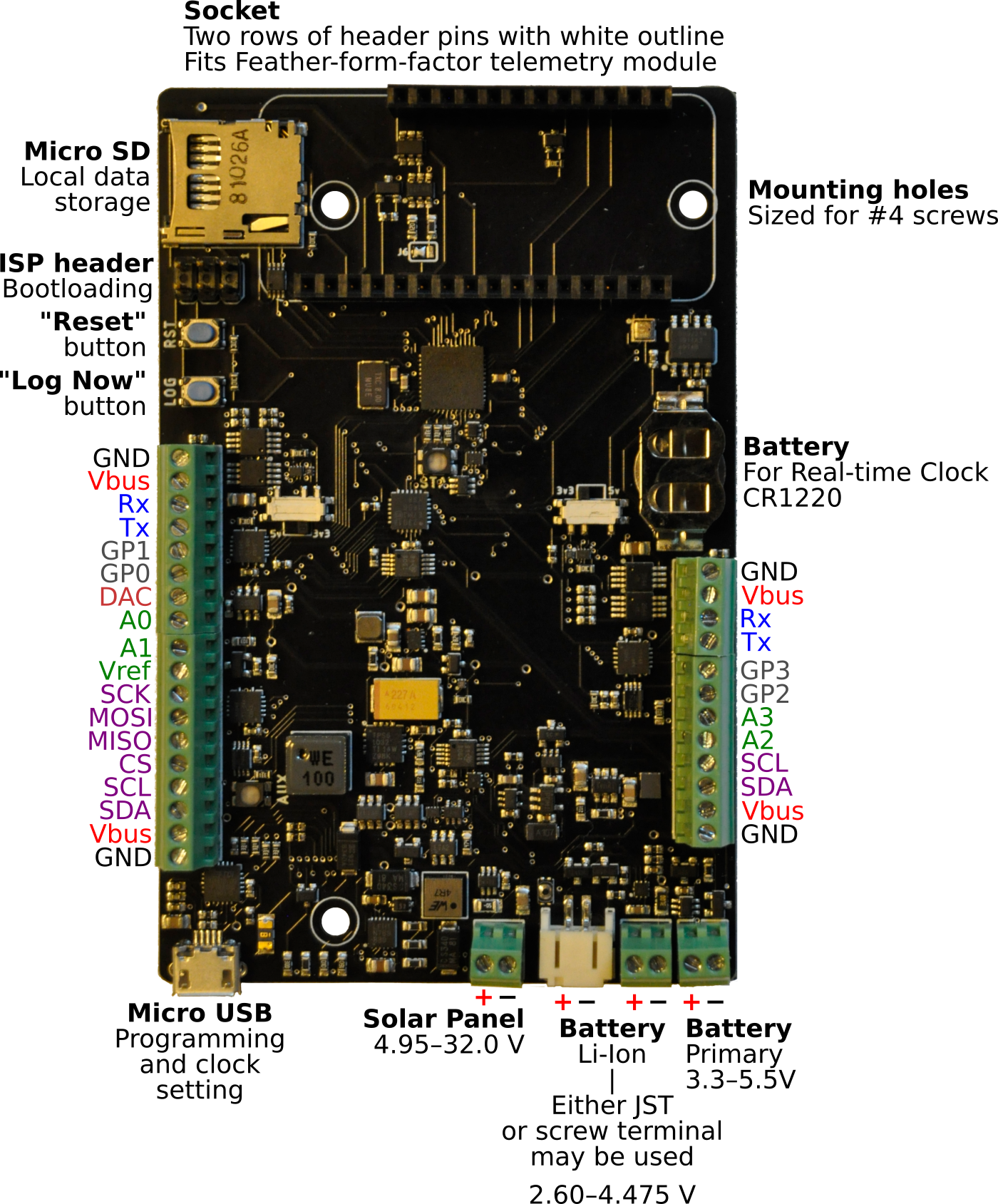
The Okapi can turn on and pass data to Feather-spec-following boards via standard digital interfaces (UART, SPI, I2C). The instructions below will be centered around the mobile-phone-telemetry Particle Boron board, with significant reference to the documents put together by the folks at Particle.
Particle Boron
Once you have your Particle Boron (datasheet), there are a few steps to follow.
Before starting, ensure that you have the proper Particle Boron for support in your country (2G/3G/LTE M1/CAT1). Note: even if you have a particular service in your country, this does not guarantee that Particle’s hardware will use it; check their website for compatability.
Standard setup
- Follow the Particle Boron quick-start guide.
- Program the Particle Boron: See code below & note the current need to set by hand the same amount of logging intervals as data-return intervals on the Okapi and Particle boards, respectively.
- Insert the Particle Boron board into the socket of a programmed (see code below) Okapi data logger.
Upon starting the system, the Particle Boron board and the data logger should function together.
NOTE: The number of log events before a data transmission is hard-coded into
Okapi.h. We need to allow this to be user-set.
Supplying your own SIM card
If you are in a country where Particle does not have a relationship with local telecom providers, you must set up the Particle Boron with your Sim card:
- Set up your device via USB (since you will not yet have mobile connection to it). This requires the Particle command-line interface – here is its reference guide, though the set-up walkthrough provides the commands you need.
- Set up your own Sim card; instructions are here (quick) and here (official).
- Program the Particle Boron (see code below & note the current need to set by hand the same amount of logging intervals as data-return intervals on the Okapi and Particle boards, respectively.
- Insert it into the socket of a programmed (see code below) Okapi data logger.
Upon starting the system, the Particle board and the data logger should function together.
Programming
Okapi
Currently, the number of data recordings made before the Okapi enables the Particle Boron is set in Okapi.h as LogCountPush. We do realize how clunky this is, and intend to streamline this.
Beyond this, no changes to Okapi are needed, and any basic code results in data transmitted through the Particle Boron.
Here is a basic script for running the Okapi with no sensors; through the Okapi library (#include "Okapi.h"), this will automatically integrate with telemetry via the Particle Boron.
okapi_no_sensors.ino
#include "Okapi.h"
// Include any sensor libraries.
// The Northern Widget standard interface is demonstrated here.
//Sensor mySensor;

// Instantiate classes
// Sensor mySensor (for any Northern Widget standard sensor library)
Okapi Logger; // Instantiate Okapi object called "Logger"

// Empty header to start; will include sensor labels and information
String header;

// I2CVals for sensors
// Add these for any sensors that you attach
// These are used in the I2C device check (for the warning light)
// But at the time of writing, the logger should still work without this.
uint8_t I2CVals[] = {};

// Number of seconds between readings
// The Particle Boron acts as a watchdog timer, and only when it is enabled;
// The allows any time interval to be used, up to the unsigned 32-bit limit
// Intervals that divide cleanly into hours are strongly preferable.
uint32_t updateRate = 60;

void setup(){
    // No sensors attached; header may remain empty.
    // header = header + mySensor.getHeader(); // + nextSensor.getHeader() + ...
    Logger.begin(I2CVals, sizeof(I2CVals), header);
}

void loop(){
    Logger.run(update, updateRate);
}

String update() {
    initialize();
    //return mySensor.getString(); // If a sensor were attached
    return ""; // Empty string for this example: no sensors attached
}

void initialize(){
    //mySensor.begin(); // For any Northern Widget sensor
                        // Other libraries may have different standards
}
Particle Boron
The Particle Boron must have the below program uploaded via the Particle Web IDE or CLI. Set BACKHAUL_NUM to equal LogCountPush inside Okapi.h. As before: We realize that this is clunky, and intend to improve this.
// Particle Boron backhaul code

#include "dct.h"

//SYSTEM_MODE(SEMI_AUTOMATIC);
SYSTEM_MODE(AUTOMATIC);
SYSTEM_THREAD(ENABLED);

#define RST D4 //Reset connected to pin 9
#define WD_DONE A3 //WD_DONE connected to pin 16
#define GPIO D14 //GPIO to micro on pin 14

#define BACKHAUL_NUM 5 //Define the number of backhaul values at a given time //FIX make flexible, just read until stop value??
String GlobalRead;
String Data[BACKHAUL_NUM];

unsigned long Timeout = 0;
// int Count = 0;

int ForceReset(String command);

// If the Particle Boron is waiting for 90 seconds with no signal from the
// Okapi, pull its RESET pin LOW -- assume it is frozen and must be rebooted.
ApplicationWatchdog wd(90000, Mayday);

void setup() {
    pinMode(GPIO, OUTPUT);
    digitalWrite(GPIO, HIGH);
    Cellular.setActiveSim(INTERNAL_SIM);
    Cellular.clearCredentials();
    // This set the setup done flag on brand new devices so it won't stay in listening mode
    const uint8_t val = 0x01;
    dct_write_app_data(&val, DCT_SETUP_DONE_OFFSET, 1);
    pinMode(9, INPUT); //Set RST as input to not interfere with rest of system
    pinMode(D7, OUTPUT);
    pinMode(WD_DONE, OUTPUT);
    digitalWrite(WD_DONE, HIGH);
    Serial.begin(9600);
    Serial1.begin(38400); //Begin to comunicate with the micro
    Serial.println("START");
    Particle.function("Reset", ForceReset);
    Timeout = millis();
}

void loop() {
    while(Serial1.available()) {
        wd.checkin(); //If any serial print made, service wd //FIX??
        digitalWrite(D7, HIGH);  //DEBUG!
        String Val = Serial1.readStringUntil('\n');
        Serial.println(Val.trim()); //DEBUG!
        if(Val.trim() == "START BACKHAUL") {
            digitalWrite(D7, HIGH);  //DEBUG!

            for(int i = 0; i < BACKHAUL_NUM; i++) { //Read data into array
                Data[i] = Serial1.readStringUntil('\n');
            }
            for(int i = 0; i < BACKHAUL_NUM; i++) { //Read data into array
                Serial.println(Data[i]); //Send the values back on USB serial //FIX! Replace with publish
            }
            digitalWrite(D7, LOW); //DEBUG!
            Cellular.on(); //Turn on cell module
            for (uint32_t ms = millis(); millis() - ms < 1000; Particle.process());
            Particle.connect(); //Connect to cloud
            for (uint32_t ms = millis(); millis() - ms < 10000; Particle.process());  // wait 10 seconds to Connect.  Boron connects in <10seconds on my desk in AutoMode.
            waitUntil(Particle.connected); //Wait until connection is complete
            Serial.println("Connected");
            for(int i = 0; i < BACKHAUL_NUM; i++) { //Read data into array
                Particle.publish("Data", (Data[i]), WITH_ACK); //Send the values back on USB serial //FIX! Replace with publish
                delay(1000);
            }
            Serial.println("Sent");

            digitalWrite(GPIO, LOW);
        }
    }
    if(millis() - Timeout > 55000) {
        pinMode(RST, OUTPUT);
        digitalWrite(RST, HIGH);
        delay(1);
        digitalWrite(RST, LOW);
        delay(1);
    }
}

// this function automagically gets called upon a matching POST request
int ForceReset(String command)
{
  // look for the matching argument "coffee" <-- max of 64 characters long
  if(command == "RST")
  {
    //Set FEATHER_EN pin high to connect power to feather
    Serial.println("RESET");
    pinMode(RST, OUTPUT);
    digitalWrite(RST, LOW);
    delay(1);
    digitalWrite(RST, HIGH);
    return 1;
  }
  else return -1;
}

void Mayday() {
   // System.sleep(SLEEP_MODE_DEEP, 60);
   pinMode(RST, OUTPUT);
   digitalWrite(RST, HIGH);
   delay(5);
   digitalWrite(RST, LOW);
   delay(5);
   digitalWrite(WD_DONE, LOW);  //Cycle VBat if in use, FIX??
   delay(1);
   digitalWrite(WD_DONE, HIGH);
   delay(1);
}
Returning data via telemetry/webhooks with Particle
- Google Sheets:
https://docs.particle.io/datasheets/app-notes/an011-publish-to-google-sheets/
- Note: defer to the relevant Northern Widget device page for device-specific code
Note: The following code requires access to a Particle account, either create or log in to one when using these links.
- Code on Particle board for backhaul (data return): https://build.particle.io/shared_apps/6091682fde87cd0008de5572
- Code on Particle board to set it up with a SIM card (for countries without Particle contracts with local telecom): https://build.particle.io/shared_apps/5ff472d9483a480017a48b79
Step 4: Recording and plotting data
Simple overview: turn on batteries, etc.
Margay / Okapi library references
We use Doxygen to auto-generate basic code referencing information, and populate this into the Readme markdown files.
Guide to Margay / Okapi field operations and LED flash patterns
Margay field and LED flash interpretation guide. Note: these LED flashes are applicable to Okapi as well.
Let’s make these more intuitive and user-friendly
Data files and SD cards
- Proper ways to swap SD cards
- Copy/pasting data files
- Example data-file contents
Google Sheets and telemetry
- Log in to Google Sheets
- Note: output might all be in a single cell – not split by columns, depending on code used to return data
Step 5: Field assembly
Recommended Tools
- Tool roll picture
- List with rationale
Example mounting structures
- Including information / pictures on attaching loggers and sensors to these structures
Example deployments
- Include photos, videos, descriptions, …, curated from multiple folks at multiple sites
- Possible ideas below
Stream gauge
Lake-level gauge?
Weather station
Glacier-ablation station
Step 6: Deployment
This could be a really short add-on to the above section, could be a way to summarize/wrap up, or could be superfluous.
Could also include troubleshooting?